Low tech : a bending spirit…
After a long absence, here I am to write again… In fact I have a lot of stuff to speak about but I haven’t enough time to write everything down… Maybe I should see my time schedule again in order to fit some time for the blog…
This time, I’ve seen a post in Digital Tools blog speaking about low tech sensors and actuators with a circuit bending spirit. This post made me obviously think on Nicolas Collins‘ work and workshop at the academy. The interesting part of his post are the links: one to a wiki that teaches how to build some low tech devices; and the other one to the lowtech.propositions website.
Thanks to this pot I got to know this architecture company website, with some interesting features (in their old website) like interactive design and artistic research.
Past week, AOC and drawing introduction…
Since last week, I didn’t had time to write on my blog. So I’ll do a short summary and talk about the things that happened. I’ve already spoken about Monday and Tuesday (second part here) in past posts, therefore, I’ll start speaking about Wednesday. We should have started the mecatronics workshop, but since there was the Mormyrophone™ workshop with Christian Graff going on, we had no class.

But we could stay there to see what was going on and how it worked. Students were working on the Mormyre (scientific name: Petrocephalus simus) a tropical freshwater fish living in Democratic Republic of Congo, Angola and Zambia that produces an electrical signal and has electroreeptors to locate itself and predators. The objective of this workshop, was to use the signals generated by the fishes as a number input on the computers.

Students developed several works using Processing, Blender and Pure Data. The generated signal variates randomly, so it can be used as an exponential random function (that explains the use of logarithm to treat the signal). The fish is although sensitive to external electric variations.
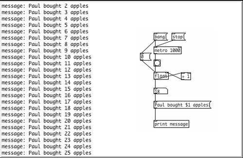
Thursday, we had our first Sound and Hypermedia AOC. We started learning the bases of Pure Data : number box; message box; object box; sum, subtract, multiply and divide objects; bang object; float object; and print object. Finally we shortly introduced the variable concept. We although saw connection between boxes and learnt that electronic sound is mainly number manipulation. We made a small program that counts the number of apples and prints a sentence on the screen.
By the afternoon, we had our first hypermedia class… We saw a number of artists like . Then we started to learn some really basic concepts like the size, ellipse and stroke objects. We although learnt some bases of color on a computer screen : the prime colors are not Cyan, Magenta and Yellow but Red, Blue, Green; and the sum of all colors don’t produce black but white. The last thing we learnt was that color values go from 0 to 255 (because it’s encoded on 8 bits). Finally we saw that shapes have two color parameters: their line and their area. We can change theme by using the line and fill objects.

Friday, we debated about what would become the “Atelier des fictions” project. We will discuss about it again next Friday.
Monday we had English class, we discussed about doing a blog in English speaking about our experience in the academy, this blog will be soon on-line. At the afternoon, we had philosophy class, this year’s topic we will be about Machine, Thought and behaviour.
Tuesday, we had drawing class at the morning. Our topic was the tool. By the afternoon teatcher were on strike.

Circuit bending app…
After all the circuit bending workshop posts, some of you asked me about the interest on circuit bending and how we could use in a creative way… Well… here is a cool video made by Gijs showing his work and what we can do with this kind of practice… So take a look on what we can do with a Game-Boy, a home-made sequencer, a camera, some lights and motors… The project name is Camera Sequencer… I although give you the project page called Gieskes.
I hope you enjoy it…
If you like technical details, here are some more comments about this project.
Another project from the same person is the Sega Mega-drive Sequencer…
Here you can see a video showing its result :
Arduino and intelligent electronic communication…
Still exploring geekdad’s blog, I’ve read a post about demotic explaining why smart houses and equipment interconnected development is so slow and how arduino can contribute for the house automation process. Arduino is indeed a cheap micro-controller interface built originally for artist and hobbyists… The great thing in arduino, besides the low price rate, is the possibility to program it and to use it to communicate between objects (like geekdad post explains), building binary or analog conversation subjects between normal, common or built objects.

The post althought speaks about this book, called “Making Things Talk: Practical Methods for Connecting Physical Objects”,that is now in my “things to buy” list…
Circuit bending, speaker hacking…
During the circuit bending workshop, I’ve learn to use and build different types of speakers and microphones… Exploring a little WIRED Magazine Home Page, Geekdad Blog section to be exact, I’ve found a note about “how to build a homemade speaker” with a link to this tutorial page…

X/Y Oscilloscope Sound Controlled Animation
Here is a link to a blog called Digital Tools showing some animations made with an oscilloscope controlled with a stereo sound signal.
First animation (the song you hear is not the sound wave form used to biuld the animation)
Second animation (this time you listen to the sound used to produce the animation)
Left and right output are connected to the X/Y oscilloscope inputs generating the visual animation.
This might be an interesting application for the device built during the Circuit Bending Workshop. I’m curious to test it to see what kind of visualisation is built with the oscillators we learnt to build.
After it… Hacking Lego…
After the circuit bending workshop, we have the Lego prototype rules violation activities… I’ve just read this post on Geekdad’s blog and made the link between both activities. When we mess up with our toys in the mecatronic workshop, we were violating “safety rules” in order to get a result from it.
And as a bonus here are some videos made with Lego:
Final round, for now…
In the last two days of the workshop we learnt how to control a switch with a NOT door oscillator and how to build an oscillator with modulation. Basically it is made with several NAND doors (that is an AND door witch the exit is linked to a NOT door, there fore it gives to opposite of the logical sum of the two entries… ok… technical crap…) built in a cascade form. The NAND door has two entries; in this case we use one as a start-up control and the second one as a pitch control. The start-up control can be seen as an automatic switch, when you have power the NAND door is ON and it works, when not, it is OFF and it stops to work. The pitch control works exactly the same way as the previous oscillator; a variable resistor controls the frequency.
Switch controlled by a NOT door oscillator:


NAND door oscillator controlled by 4 light sensitive resistors and a potentiometer:
Final production:


The difference between this oscillator and the previous one in multiple exit addition is the output shape. The NOT oscillator adds the signals, so we have a sound that is the result of a sum. The NAND door modulates the signal, which means it changes the signal shape. With constant resistors you may not see the difference between both oscillators. But when you start to vary the resistances, you’ll see that the way the sound changes is different.
The last day of the workshop was used to solder the final circuit. We have made a small demonstration for the people who were in my art academy and we cleaned up all the mess we did the last six days.
I will end up this post with a video from a Electroacoustic instrument called Rectable :
This instrument works with several oscillators (controlled by the computer) in signal addition mode and signal modulation mode.
Rock around the clock…
Today, we started the day rocking some toys’ circuit’s clocks. Electronic circuits have clocks inside in order to have a time base for the rest of the circuit to work. If you change this time base, the other components of the circuit will run faster or slow down. There are two ways to build a clock in electronics (in fact there are more ways but this two are the most common and simple ones): you can use a crystal or you can use a resistor and a capacitor. The resistor and the capacitor is a really cheap solution and we can find theme in many cheap games; the good thing is that they are easy to find and to change. To find theme we only need to use wet fingers and patience: you touch the components and you listen to see if you get some slow motion effects. Then we have to change the resistor into some other kinds of variable resistors (photo resistor, variable resistor, pressure resistor, etc.). Each kind of variable resistor can be seen as a single interface with its own characteristics, a little like instruments: a saxophone and a guitar can play the same notes but the musicians don’t play a guitar like he plays a saxophone. A little anecdote about the title of this post, the first time I understood that the speed reading a record can change its pitch was with the song Rock around the clock, I played it in a 45 rotation mode and the record was in 33, something like this… And since we are playing with clocks and pitch, I remembered this funny experience.
After the interface exploration, we started to learn something really technical: building oscillators. Building an oscillator starts with some basic logics. Using NOT doors (that is a logical function), we generate a signal that is the opposite of the entry: when the entry is low the output is high, when the input is high the output is low. So if you take the output and plug it back to the input, the signal oscillate from low to high and low and high, and so on…This generates a square shape wave.

But the problem is that the oscillation happens really fast and we don’t have a way to control its frequency. So we have to put something to slow down the signal changes. We do it simply with a capacitor and a resistor. The capacitor loads itself slowly and unloads fast; the speed that the capacitor does this is linked to its capacity and the resistance of the resistor.

When we plug this to the NOT door, we build an oscillator. If we use a variable resistor we can control oscillation frequency. That’s how we build a square signal generator. This square signal has amplitude set between 0V and the battery voltage (in our case 9V), so we can control a speaker or LEDs, fans, etc. When the signal is low the component controlled is off, when its high the component switches on.

Since the chip has 6 NOT doors, we can build a system that generates six different signals, with six capacitors and resistors. The problem is, if you add all six signals you will have a gain too high, so when you link the signals, you do it in parallel and you add a resistance to control the signal gain. The resulting sound is an addition of all signals together. Each “channel” can have its own indepedent interface.

First day, first experiences…
We started the workshop making simple experiences with sound.

The first experience was to use a speaker, wires and a 9V battery to generate sound, thanks to feedback. We take two wires, we put one of theme on the speaker’s membrane and we approach the second wire in order to make contact. Surprise: we generate a sound that is specific to that particular speaker (it works on all speakers). What happens is that the speaker’s membrane vibrates making the contact go on and off witch produces the frequency we can hear.

Ok… This was sweet and easy… And what if we take the two wires and we “taste” the materials around us? So we started to play with materials fixing one wire and scratching the second on it. The result is some strange sounds. The material’s asperity (more or less visible) makes the scratched wire to close and open the circuit, generating frequencies that we can hear.
Ok, so with a battery, some wires, a cheap and old speaker, we can actually make sounds… Hum… Interesting… No amps, no expensive and complicated electronics… Ok… But let’s try to put some electronics on it…
The speakers and microphones are built the same way… The main difference is that they are originally built for a specific function (to generate sound from an analogical signal; to generate an analogical signal from a sound). “Normally” you put the speaker in the output of an amplifier and the microphone in the input. But, if you put a speaker in the output and another one in the input, you will find out that the speaker plugged in the input works like… a microphone! Oh what a surprise! The main difference between a microphone and a speaker used as a microphone, besides the visual aspect, is the sound signal generated. Using different speakers as a microphone modulates the sound in different ways… And if we put the speakers in front of each other, cool sounds come out…

Another device used to generate sound is the buzzer… The buzzer is basically a crystal that vibrates when electricity goes thought it. But, if you vibrate the crystal, you have electricity production, therefore a sound signal. So, if we put a buzzer in the input of an amplifier and a speaker in the output we should hear something…. But the buzzer only generates sounds when the crystal vibrates, and the crystal is a solid, not a membrane, so it needs more energy to vibrate. So buzzers are able to record strong vibrations (like in solids). This makes us able to record cool sounds that are produced inside materials (like ice melting).

Like the speaker used as a microphone, you can use the buzzer and the output speaker in a feedback mode, here is an example of what you can do, basically, we taped the buzzer to the plastic glass and connected it in the input of the amplifier. The sound produced makes the glass (and the buzzer) jump and produce sound witch makes them jump, etc.
After this we discovered a nice device that reproduces the electromagnetic waves to a sound signal. The cool thing is that you can copy a signal and amplify it with no electric contact. This device was used to spy phone calls (now the armies must have more high tech devices for that… I guess…) , but you can use theme to spy all kind of electromagnetic generator devices (like a computer, or a circuit)… This device can’t be used to produce sound, only to generate signals…
The last component we saw to produce sounds as a microphone was a magnetic head. The magnetic head is able to read data on magnetic tapes or cards. The head generates an electric signal that can be converted into sound.

Finally, we used radios to generate some strange sounds by opening theme, licking our fingers and playing with the circuits.
